Making a Part
|
|
This page goes through a typical sequence of steps in order to make a part using CNC.
|
|
|
|
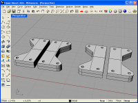
Create the Model
I use a CAD program called Rhino 3D.
I start by creating a 3D model of the part. I use the 3D model so that I
can combine all of my parts into the finished product and check the finished
product to make sure everything will work together. In reality, you can often
use a 2D CAD program to design your parts. For those of you with
Rhino, here's the
Upper-Mount.3dm file.
Bigger...
|
|
|
|
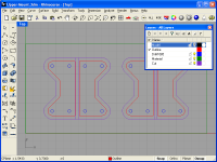
Create the CAM features
The next step is to decide what machining operations you're going to perform,
and create contours or other supporting objects that will be used by the
CAM program. I normally use features from the 3D model to create the
CAM objects. In this photo, you can see a green rectangle which represents
the material which will be machined. The red outlines are the outline of
the part. The blue circles represent holes which need to be drilled.
I also like to double check the cut, so I offset the red contour diameter
of the endmill I'll be using. This lets me make sure that the cutter won't
interfere with anything. I then select all of the objects (except the
purple lines) and export them into the
Upper-Mount.dxf file.
Bigger...
|
|
|
|
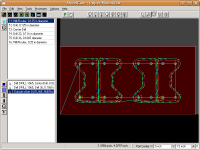
Generate the G-Code
I use a program called SheetCam to
generate my G-Code. It takes a DXF file as input and generates the G-Code.
Incidently, I'm running SheetCam on my linux Ubuntu distribution, by using
wine. SheetCam uses a notion of "Processes". In this particlar job, you can
see three. The first process center drills each of the holes, the second
process drills the holes, and the third process machines the outlines.
SheetCam also has a rather nifty feature called "tabs". These can be seen
by the short blue segments in the red outline. The tabs are small amounts of
material which get left behind to leave the piece attached to the material.
You'll be able to see the tabs in the G-Code simulation in the next photo.
Here's the SheetCam job file: Upper-Mount.job
along with the generated G-Code file:
Upper-Mount.nc.
Bigger...
|
|
|
|
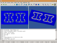
Simulate the G-Code
I then take the G-Code produced by SheetCam
and use CutViewer Mill to verify
the G-Code and ensure it's going to produce the correct part. You can see
the tabs in this screenshot.
CutViewer will also check for
collisions (i.e. trying to rapid through uncut material). It doesn't
have any capability to check for collision with clamps (and I've run into
my clamps a few times :)
You can also do cross sections and take measurements from the simulation
as well. CutViewer Mill is also being run on my linux box using wine.
Bigger...
|
|
|
|
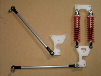
The finished part
Here you can see the finished part (in the top right corner of the picture)
along with some other pieces. The shocks and ball ends were purchased.
Bigger...
|
|
Home
- Machinist
- CNC
|