|
The next step is to decide what machining operations you're going to perform,
and create contours or other supporting objects that will be used by the
CAM program. I normally use features from the 3D model to create the
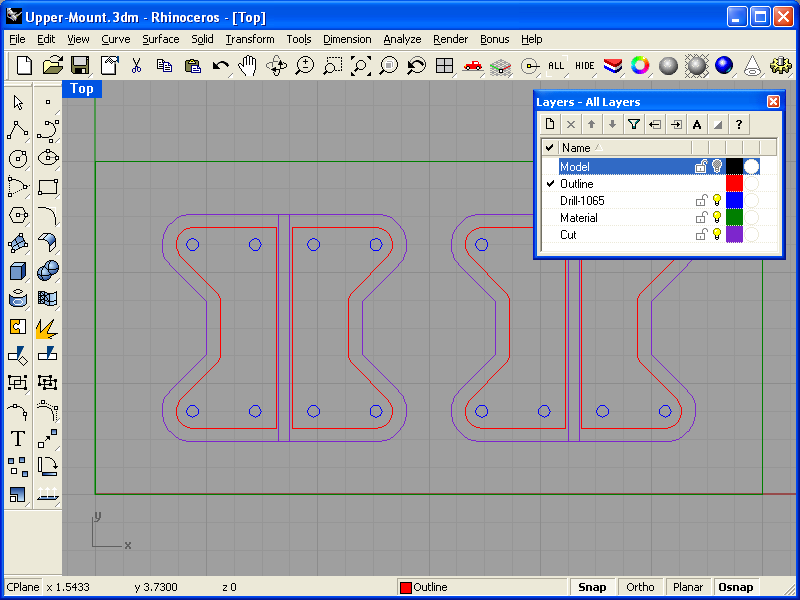
CAM objects. In this photo, you can see a green rectangle which represents
the material which will be machined. The red outlines are the outline of
the part. The blue circles represent holes which need to be drilled.
I also like to double check the cut, so I offset the red contour diameter
of the endmill I'll be using. This lets me make sure that the cutter won't
interfere with anything. I then select all of the objects (except the
purple lines) and export them into the
Upper-Mount.dxf file.
Bigger...
|
|