|
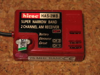
I've often wanted to connect an RC Transmitter/Reciever up to a robot
for testing purposes, but didn't want to use one input per channel.
|
|
|
|
|
|
|
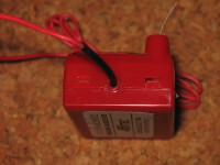
Holding tabs
My receiver has 4 little tabs holding the top and bottom halves together.
After cutting through the labels on the sides, I found that you could very
gently push on the tabs through the holes in order to separate the top
and bottom of the case.
Bigger...
|
|
|
|
Inside Top
Here we see the top removed. Notice that there is an extra row of
locations to plug pins into above the two channels of pins already
present.
Bigger...
|
|
|
|
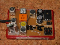
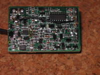
Inside Bottom
Ah Ha. Pay dirt. The surface mount chip in the top right is an
HEF40175B
chip, which is a quadruple D type flip flop, which can be arranged to
look like a shift register. Sure enough, the signal lines on the two
servo outputs which are present go directly to the output of the D-flops.
In fact, the unpopulated pins appear to be for a 3rd channel.
Bigger...
|
|
|
|
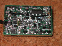
Bottom Modification
So, I cut the trace leading to the extra signal line. You can see the cut
just above the top-right of the HEF40175B. The output was originally
connected to pin 2. I determined that a nearby resistor was connected
directly to pin 9 (the clock) so I then added a piece of blue wire wrap wire
from that resistor to the unused channel pin.
Bigger...
|
|
|
|
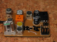
Top Mod
Here you can see I soldered in an extra pin into the "unused" channel.
By adding an extra pin, I was still able to use the receiver in it's
original form.
Bigger...
|
|
|
|
Case Modification
I added an extra hole in the case to get at the new pin. I was orignally
going to make a bigger slot for all 3 pins and decided in the end to just
use one.
Bigger...
|
|
|
You can find some source code in the RCInput.c file.
|
|
Home
- Line Maze 2006
|