Brute
|
|
Brute is a "Lightweight Sumo". It starts out inside a 15cm x 15cm square and
weighs just under 1 kg. It took me about 60 hours to get everything to
fit in it's present incarnation.
Brute is 100% Lego, has a pnuematic lift on the front, and uses antenna
feelers to detect opponents. I'm not sure how well it will do against
other "Lightweight Sumos" because I haven't come across any others yet.
|
|
|
|
|
|
|
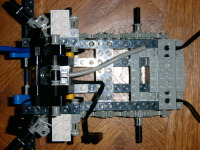
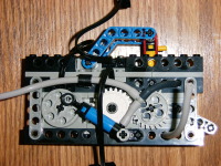
Chassis from Above
This is a view from the top. The motors are on the right hand side.
You can see the antenna feelers angling out at the top and bottom of the left
hand side of the picture.
Bigger...
|
|
|
|
Chassis from Below
This is a view from the bottom. My apologies for it being blurry. At the
top, you can see two touch switches and the light sensor.
Bigger...
|
|
|
|
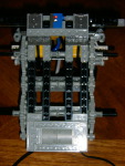
Chassis from the Side
It looks like there isn't much holding the motors in, but they are rather
secure. The motors have little slots on each side (two are visible on the
left edge of the motor) The black beam attaches at the top, and there are little pieces that
fit into the slots (behind the 40 tooth gear) and this seems to provide
fairly rigid support.
Bigger...
|
|
|
|
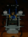
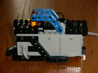
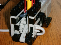
Pneumatics from the Back
Here's a picture of most of the pnuematics. The blue piston is a pump, and
it is driven by the motor on the left side. The middle motor has a white
clutch gear (slips rather than stalling the motor if it can't rotate) and
is used to control the pneumatic switch. There is an 8 tooth gear connected
to the same shaft as the gray 24 tooth gear. This drives another 24 tooth
gear which is connected to the pneumatic switch.
Bigger...
|
|
|
|
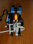
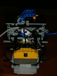
Pneumatics from the Front
The pneumatic unit from the front (the boring side). You can see the
pneumatic switch on the left hand side. The black angled piece provides
some reinforcement.
Bigger...
|
|
|
|
|
|
|
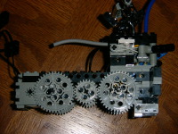
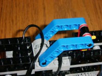
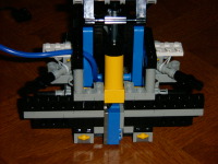
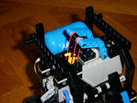
Pressure Regulator
This is a closeup of the pressure regulator. As the air pressure builds up,
the yellow piston will raise. The blue angled pieces connect to a Lego
polarity reversal switch. These switches have a dead zone, and when the
pressure is high enough, the switch enters the dead zone and the pump motor
turns off. When the pressure drops, the red elastics pull the piston down and
cause the switch to reactivate the pump motor. This is basically just a copy
of Ralph Hempel's design.
Bigger...
|
|
|
|
|
|
|
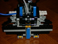
Piston Down
Here we can see the pneumatic piston used to lift the fork-lift at the front.
This is in the down position.
Bigger...
|
|
|
|
Piston Up
And here it is in the up position. If you look carefully at
the previous picture, you will notice a total of 5 sensors. There are three
along the bottom (two touch switches and a light sensor). On the left side
of the photo, just below the blue tubing and to the right of the white
elastic band, you can just make out the yellow portion of another touch
switch. This is for the antenna feeler. There is another one in the same
place on the right hand side. What! you say the RCX only has 3 inputs!
Bigger...
|
|
|
|
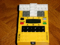
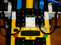
RCX Wiring
Each antenna feeler goes to a separate RCX input. The light sensor and the
two touch switches on the bottom are all connected in parallel. The touch
switches are normally open, and the light sensor value is read on the input.
If either touch sensor is activated, then the light sensor reads 100%.
Bigger...
|
|
|
|
|
|
|
|
|
|
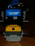
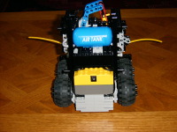
Air Tank Mounted
Here we can see the air tank and the 9v battery holder which is used to
provide power to the pump. The pump is completely isolated electronically
from the RCX, and keeps the air tank pressurized all by itself.
Bigger...
|
|
|
|
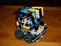
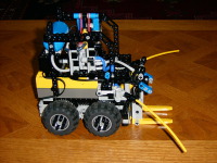
Fully Assembled
Here we can see everything put together. Notice that there is a little gap
between the bottom of the fork lift and the touch switches at the bottom.
When the lift bumps into something, it signals the program to activate the
lift. Encountering the white line at the edge of the ring causes the lift
to be lowered. The black pins in the center of the wheels are to keep
another robot from hitting the rubber portion of the wheels and making them
hard to turn.
Bigger...
|
|
|
|
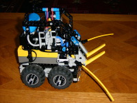
Starting Position.
At start time, the robot has to fit within a 15 cm square. This is what it
looks like. It backs up a bit at the beginning, which causes the antenna
feelers to pop out. Lowering the piston causes the forks to fall down.
Bigger...
|
|
|
|
|
|
|
|
|
|
|
|
|
|
|
|
|
Home
- Line Maze 2006
- Lego
|