CNC Spindle Encoder
|
|
Well, I finally got around to connecting up the steppers on my lathe.
The next obvious thing to do was to add a spindle encoder so that I can
do threading.
|
|
|
|
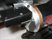
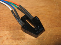
Spindle Encoder
The spindle encoder looks pretty boring in the box. The two whitish circles
are pieces of plexiglass that I turned so I could see the LEDs inside. If I
had thought about it a bit more, I would have had the LEDs poking out the
top. The aluminum spindle reflects infrared really well, and a piece of
black electrical absorbs the infrared acting as an interruption.
Bigger...
|
|
|
|
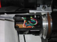
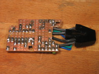
Cover Off
Here you can see how the sensor is mounted, and you can see the insides
of the encoder. I made the mount from a piece of sheet aluminum and cut
it freehand using my metal bandsaw.
Bigger...
|
|
|
|
|
|
|
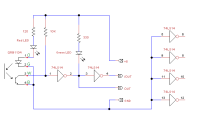
Schematic
This is the schematic for the encoder. I created it using a rather nifty
little program called TinyCAD
which is a free schematic capture program. The O, G, W, and B letters
next to the QRB1134 correspond to the wire colors which come attached to
the sensor.
This is the TinyCAD schematic file: CNC-Spindle-Encoder.dsn.
Bigger...
|
|
|
|
Sensor Closeup
This is a closeup shot of the sensor. The E side corresponds to the emitter
and is basically an infrared LED. The S side corresponds to the sensor and
is a phototransistor. Optimal distance is about 0.150" from the sensor to
the refletive surface.
I bought mine from
The Mark III Store
but you can also get them from Digi-Key
or Mouser.
Bigger...
|
|
|
|
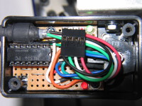
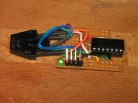
Circuit Board
The circuit board out of the box. I used a 4 pin connector so I could
disconnect it. The 74LS14 was from my junk box. I left the leads a little
long from the sensor so I could adjust it, if required.
Bigger...
|
|
|
|
|
|
|
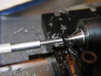
First Part
This is my first threaded part using the CNC threading capability from
Turbo-CNC. This piece is cut from
a 1/4" steel rod (CRS - not leaded). The thread is 4mm x 0.7mm (cut using my imperial lathe
- which doesn't really matter with CNC).
I created the G-Code for the basic outline using CAD2Lathe and added the
threading passes by hand. Unfortunately, CAD2Lathe doesn't seem to be
sold anymore.
The gouge out of my live center was caused by me crashing the lathe :(
I entered the position of the toolbit using the diameter rather than the
radius and the computer happily tried to drive the toolbit somewhere on
the other side of the live center - whoops. It also chipped the end
of the carbide toolbit. Good thing I had a spare.
I'm thinking that I should setup Turbo-CNC to use diameter mode. Firstly,
when you measure anything on the lathe you always measure the diameter.
Secondly if you screw up and enter the radius as the position, the worst
thing that happens is that you don't cut anything at all rather than
crashing.
Bigger...
|
|
|
Here's Mark Wrathall's
spindle encoder, which uses a slightly different design.
|
|
Home
- Machinist
- CNC
|